UC3843 Current Mode PWM Controller IC Explained: UC3842 vs. UC3843, Datasheet Features, Pinout, Sample Circuits, Equivalent ICs
UC3843 Current Mode PWM Controller IC: UC3842 vs. UC3843, Datasheet Features, Pinout, Circuit, Equivalent ICs
Introduction of UC3843 PWM Controller IC
The UC843 is essentially an active mode Pulse Width Modulation (PWM) controller with a fixed frequency. It also could be described as the UC3843 buck converter. It is designed to be used for DC to DC converter functions and offline applications and needs only the smallest external components. The UC843 comes in three packages that will be described in the following sections.
The IC UC3843 comes with a variety of characteristics that make it suitable for a wide range of real-world applications. The features include an oscillator that is trimmed for the purpose of controlling of precise duty cycle, a high-gain amplifier, and regulating power MOSFET, and an output totem pole with a high current. Additionally, other options include temperature compensated reference as well as a current sensor.
Features of UC3843 MOSFET
Current-Mode PWM controller
Operating Voltage: 7.0V to 8.2V
Output pin current: 1A
Analog input range: -0.3 to 6.3V
Oscillation Frequency: 52 Typically
Gain: 3V
Maximum source current: 22mA
Low Output Voltage: 0.08V
High Output Voltage: 13.5V
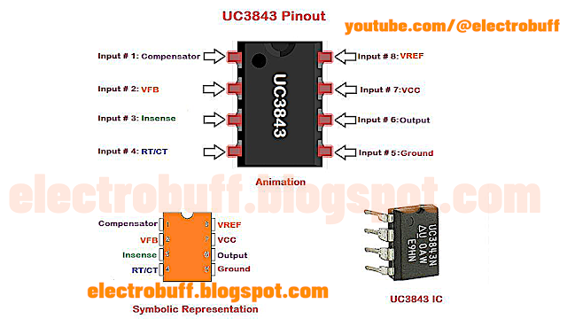
UC3843 Pinout
The UC843 features eight output and input pins. Four pins are located on the left side and four pins are to the right of the IC. Below is the UC3843 Pinout:
 |
| uc3843 IC Pinout electrobuff.blogspot.com |
 |
| uc3843 IC Pinout description electrobuff.blogspot.com |
| Number | Pin Name | Description |
| 1 | COMP (Comparator) | This pin is one that produces a low impedance single-frequency 1MHz dependent on the variation between the set and current-voltage. It is usually linked to the voltage feedback port on the IC by means of a resistor and capacitor. |
| 2 | VFB (Voltage Feedback) | It's an input for the error amplifier in the IC. The difference in voltage is fed via this port. |
| 3 | Current Sense | A shunt resistor can be used to measure the flow of current through the circuit. The voltage it generates is used by the pin that senses current. |
| 4 | RT/CT (Timing Resistor/ Timing Capacitor) | The IC UC3843 is equipped with an internal oscillator, which can be adjusted with an external resistor as well as a capacitor that is connected to this pin. |
| 5 | Ground | Connected to the ground of the circuit. |
| 6 | Output | This pin produces PWM signals based on the feedback that is provided. We can utilize this signal to turn off the device's power source. |
| 7 | Vcc | Supply voltage for the IC (Nominal 11V) |
| 8 | VREF | Reference voltage on the voltage at which the PWM signal is generated. |
Specifications
Supply Chain
Factory Lead Time - 6 Weeks
Physical
Number of Pins - 14
Weight -122.413241mg
Technical
Operating Temperature - 0°C~70°C TA
UC3843 Circuit Diagram
Below is the UC3843 IC circuit diagram:
 | |
|
Where to Use UC3843 IC?
Due to the features of the UC3843 buck converter, it is suitable in SMPS (Switch Mode Power Supplies) circuits, DC-DC converter circuits, electronics power supply, battery drain circuits, as well as load machines.
UC3843 Equivalent
You could use UC3842 as the UC3843 equivalent. You could find them on easybom.
How to Use IC UC3843?
The UC3843 IC is a complex device, however, its use of it in circuits is quite easy. The IC includes under-voltage protection therefore care must be taken to insure that it is operating at a voltage of 7V to 8.2V. This output connector of IC can be connected with the circuit for gate drivers in the Power switch, which has to be turned off. The output pin is able to generate up to 1A, and hence a limiting resistor for current is needed. Its VFB (Voltage feedback) pin functions as a feedback pin based on this signal that can be controlled. Shunt resistors are used to track the fluctuation in current within the circuit. This difference in voltage across the shunt is transferred for feedback to the pin.
Below is the UC3843 application circuit diagram:
 |
| uc3843 IC DC DC Boost Converter Circuit electrobuff.blogspot.com |
Everything You Need to Know About UC3843 IC in Electronics
UC3842 vs. UC3843
What is UC3842?
The UC3842 is a fully integrative pulse width moderator (PWM) made with these goals in mind. This IC gives designers a cost-effective controller, with which they can enjoy all the advantages of operating in the current model.
What is UC3843?
UC3843 is essentially the current-mode Pulse Width Modulation controller. It was specifically created to be used in DC to DC converters as well as offline applications. It performs its duties with the minimum requirement for external components, thereby avoiding complications. It is extremely popular due to its unique capabilities such as current sensing, high-gain amplifiers, and high current totem pole out to control the operation of MOSFET. The UC843 ic is a suitable component for transformer-coupled DC to DC converters, etc.
Applications of UC3843 IC
SMPS (Switch Mode Power Supplies) circuits
DC-DC converter circuits
Electronics power supply
Battery drain circuit
Load machines

.png)


.png)


.png)


Leave a Comment