555 Timer IC and how it works Explained
How a 555 Timer magic IC works

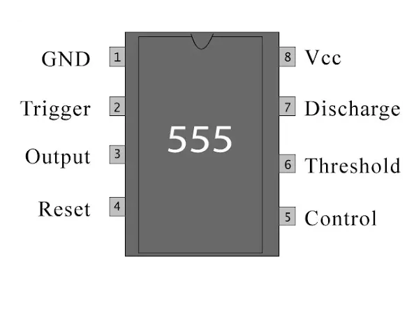
555 Timer IC Pinout and Internal Block Diagram

Introduction:
The 555 timer IC is
a versatile integrated circuit widely used in electronics as a timer, pulse
generator, and oscillator. The 555 timer IC is a powerful and widely used
component in electronic circuits, providing a reliable and easy-to-use solution
for various timing applications.
The 555 timer is an
integrated circuit (IC) widely used in electronics for various timing and pulse
generation applications. Introduced in 1972 by Signetics (now a part of ON
Semiconductor), the 555 timer has become a staple component in countless
electronic circuits due to its versatility and ease of use. Its three operating
modes, astable, monostable, and bistable, make it suitable for a wide range of
applications.
The 555 timer's
enduring popularity is attributed to its simplicity, reliability, and
versatility, making it a fundamental building block in electronic design for
both beginners and experienced engineers.
Below is a tutorial
explaining how the 555 timer IC works, its pinout, and their functions.
Understanding the 555 Timer IC:
Pinout:
The 555 timer IC
typically comes in an 8-pin dual in-line package (DIP). The pins are labeled as
follows:
GND (Pin 1):
Ground: Connect to
the ground reference of the circuit.
TRIG (Pin 2):
Trigger: Used to
trigger the 555 timer by applying a voltage lower than 1/3 of the supply
voltage.
OUT (Pin 3):
Output: The pulse
or square wave output of the 555 timer.
RESET (Pin 4):
Reset: Active-low
input that resets the internal flip-flop when pulled low. Usually connected to
VCC for normal operation.
CTRL (Pin 5):
Control Voltage:
Used to provide an external voltage reference for the internal comparators. It
influences the threshold and trigger levels.
THR (Pin 6):
Threshold: The
inverting input of the internal comparator. When the voltage at this pin
exceeds 2/3 of the supply voltage, the output is switched.
DISCH (Pin 7):
Discharge: Used to
discharge the timing capacitor to ground when the output is low.
VCC (Pin 8):
Positive Supply
Voltage: Connect to the positive supply voltage of the circuit.
The IC 555 timer is a chip used in various areas and applications like pulse generation, an oscillator, and a timer. The 555 Timer is designed using 25 transistors, 2 diodes and 15 resistors.
The functional parts of the 555 timer IC include a flip-flop, voltage divider & a comparator altogether. The main function of this IC is to generate an accurate timing pulse for operating various devices and electronic components.
Internal Block Diagram:
The 555 timer
consists of two voltage comparators, an SR flip-flop, a discharge transistor,
and a resistor divider network. The internal block diagram is as follows:

555 Timer IC internal Block Diagram
Voltage Comparators
(Upper and Lower):
The upper
comparator monitors the voltage at the THR pin.
The lower
comparator monitors the voltage at the TRIG pin.
SR Flip-Flop:
The flip-flop
controls the state of the output.
Discharge
Transistor:
Connected to the
DISCH pin, it discharges the timing capacitor to ground.
Resistor Divider
Network:
5kilo Ohm resistors connected between
VCC and GND, it provides voltage references for the comparators.
How It Works:
Astable Mode (Oscillator):

555 timer IC Astable mode circuit
Connect the TRIG and THR pins.
Connect a resistor
(R1) from VCC to the CTRL pin.
Connect a capacitor
(C1) from CTRL to GND.
The OUT pin
generates a continuous square wave.
 |
| 555 timer ic astable mode signal waveforms |
Functions as an
oscillator, generating a continuous square wave output.
Commonly used for
applications such as LED flashers, tone generators, and clock pulses.
Monostable Mode (One-Shot):

555 timer IC monostable circuit
Connect the TRIG
and THR pins.
Connect a resistor
(R1) from VCC to the CTRL pin.
Connect a capacitor
(C1) from CTRL to GND.
Apply a trigger pulse
to the TRIG pin.
The OUT pin
produces a single pulse.
 |
| 555 timer IC monostable signal waveforms |
Operates as a
one-shot timer, producing a single output pulse in response to a trigger.
Widely applied in
applications like pulse-width modulation, time-delay circuits, and
touch-sensitive switches.
Bistable Mode
(Flip-Flop):
 |
| 555 timer IC bistable mode circuit |
Connect TRIG to THR
internally.
Connect a resistor
(R1) from VCC to the CTRL pin.
Connect a capacitor
(C1) from CTRL to GND.
Use an external
trigger to set and reset the flip-flop.
 |
| 555 timer ic bistable mode signal waveforms |
Functions as a
flip-flop, allowing for the storage of binary information.
Used in toggling
applications, such as flip-flop circuits, where external triggers can set or
reset the output state.
Example Formulas:
Frequency in
Astable Mode:
f = 1.44 / ((R1 +
2*R2) * C1)
Pulse Width in
Monostable Mode:
t=1.1⋅R⋅C
Typical Applications:
• It is used for Pulse, Waveform, and square wave generation.
• It is also used in time delay generation, precision timing, and sequential timing.
• It can be used as a mono-stable multi-vibrator and a-stable multi-vibrator.
• It is mostly used in PWM (Pulse Width Modulation) & PPM (Pulse Position Modulation).
• Used in Tachometers & temperature measurement.
• Commonly used in DC Voltage Regulators.
• Used for conversion like Voltage to Frequency Converter.
• It is also used in Frequency Divider.
• It is used in the Pulse detector.
• It can be used to design a Timer Switch.
. used in educational settings to teach basic electronics principles due to its straightforward design
and multiple applications.


.png)


.png)


.png)


Nice job man. Helped me in my watch project
ReplyDelete555 is ageless
ReplyDelete