Tl494 10,000Watts Inverter Circuit
TL494 10000Watts INVERTER Circuit 12V to 220V DC to AC
TL494 10kW Inverter Complete Circuit Diagram
%20.png)
TL494 10kW Inverter Circuit electrobuff.blogspot.com
#TL494 #INVERTER #ELECTRONICS
Hello viewers. Today I'll show you how to make an Inverter (DC to AC Converter) to step up 12V to 220V. The circuit is based on the TL494 General purpose PWM driver IC. With this, you can also alter the shape of the output AC waveform and vary the dead-time to get a modified sine wave AC of varying RMS values.
For the Transformer use a 12-0-12V to 220V AC one. If you Salvage one, retain the original mains primary winding if its not damaged, then make your own secondary center tapped winding (it will be the primary afterwards). Make about 10 turns and connect the original primary to mains, measure the voltage on your custom winding, and by relating the mains voltage, output voltage and custom winding turns, you can make an accurate estimate on the number of turns of the original mains winding. Now complete your custom winding to give you a step up ratio of 1:20. I hope you enjoy.
Watch my Inverter Video Tutorial on YouTube
%20.png)
TL494 PWM IC Basics:
The TL494 is a widely used Pulse Width Modulation (PWM) control IC that plays a crucial role in electronic circuits, especially in power supply applications. It was developed by Texas Instruments and has been a popular choice for designers due to its versatility and reliability. The TL494 is commonly employed in applications such as power inverters, switch-mode power supplies, and motor control circuits.
TL494 Pinout Description:
 |
| TL494 PWM IC PINOUT AND BLOCK DIAGRAM electrobuff.blogspot.com |
The TL494 comes in a 16-pin dual-in-line (DIP) package. Here is a brief description of its pinout:
Pin#1 and Pin#2 (1 IN+ and 1IN-) : These are the non-inverting and inverting inputs of the error amplifier (op amp 1).
Pin#16, Pin#15 (1 IN+ and 1IN-) : As above these are the non-inverting and inverting inputs of the error amplifier (op amp 2).
Pin#8 and Pin#11 (C1, C2): These are the outputs 1 and 2 of the IC which connect with the collectors of the respective internal transistors.
Pin#5 (CT): This pin needs to be connected with an external capacitor for setting the oscillator frequency.
Pin#6 (RT): This pin needs to be connected with an external resistor for setting the oscillator frequency.
Pin#4 (DTC): It's the input of the internal op amp which controls the dead-time operation of the IC.
Pin#9 and Pin#10 (E1 and E2): These are the outputs of the IC which connect with emitter pins of the internal transistor.
Pin#3 (Feedback): As the name suggests, this input pin is used for integrating with an output sample signal for a desired automatic control of the system.
Pin#7 (Ground): This pin is the ground pin of the IC, which needs to connected with the 0 V of the supply source.
Pin#12 (VCC): This is the positive supply pin of the IC.
Pin#13 (O/P CNTRL): This pin can be configured for enabling the output of the IC in the push-pull mode or single ended mode.
Pin#14 (REF): This output pin provides a constant 5V output which can be used for fixing a reference voltage for the error op amps, in the comparator mode.
TL494 PWM IC Error Amplifiers:
The TL494 includes two error amplifiers, each with its inverting and non-inverting inputs. These error amplifiers are crucial in the regulation process. They compare the feedback voltage (representing the output voltage) with a reference voltage and generate an error signal. This error signal is then used to adjust the duty cycle of the PWM waveform, regulating the output voltage. |
| TL494 PWM IC internal block diagram electrobuff.blogspot.com |
TL494 PWM Control:
To use the TL494 for PWM control, you typically connect the feedback pin (FB) to a voltage divider network across the output. This network provides a fraction of the output voltage to the FB pin, allowing the error amplifiers to compare it with the internal reference voltage.
The RT and CT components set the frequency of the PWM waveform, and the dead time control pin helps prevent overlap between the upper and lower switching transistors.
 |
| TL494 PWM IC frequency formula calculator electrobuff.blogspot.com |
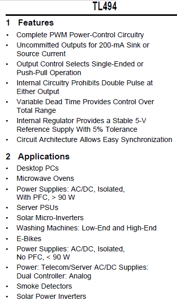
TL494 PWM IC Features:
- Wide operating voltage range.
- Adjustable dead time control.
- Internal voltage reference.
- Error amplifiers for precise regulation.
- Soft start capability.
- Output control for shutdown or protection.
- Dual PWM outputs.
TL494 PWM IC Applications and uses:
- Power Supplies: Used in switch-mode power supplies for regulating output voltage.
- Inverters: Commonly employed in power inverters for converting DC to AC.
- Motor Control: Used in motor control circuits for driving motors with variable speed.
- Voltage Regulators: Suitable for applications requiring precise voltage regulation.
- Battery Chargers: Employed in battery charger circuits for controlling charging current.
 |
| TL494 pwm ic features and applications electrobuff.blogspot.com |
The TL494's flexibility, ease of use, and reliable performance make it a preferred choice in various power electronics applications
Related Videos:
1. TL494 Adjustable Switching Power Supply for DIY Projects 1-120V 250W
Link: https://youtu.be/p-HBa85AdKw
2. TL494 2000W Power INVERTER with Modified Sine Wave Output
link: https://youtu.be/a-t2_5pSfcg
3. IR2153 Switching Power Supply 50-0-50V for Amplifier
link: https://youtu.be/b6Luryjd1jo
4. SG3525 Regulated Inverter 600W full Bridge
link: https://youtu.be/yipXbDlH0Z4
5. 5000W Inverter with IR2153 12V to 220V DC to AC
link: https://youtu.be/4nAQGTPSs0A
6. TL494 Modified Sine Wave Inverter
link: https://youtu.be/rFpdCwieseg
7. UC3842 Switch Mode Power Supply 3-15V at 10A
link: https://youtu.be/eTd_1wOxBr8
8. TL494 Adjustable Switch Mode Power Supply (DC DC boost smps) 1-50V 400W
link: https://youtu.be/bBgsszmleJY
9. TL494 Switching Power Supply for Power Amplifier 50-0-50V
link: https://youtu.be/fRnSoUzHnnE
10.TL494 Professional Voltage Booster 12-120V (DC DC boost converter)
.png)


.png)


.png)


Leave a Comment