TL494 PWM IC Tutorial : How to use in Power Supplies & Inverters
TL494 PWM (Pulse Width Modulation) IC Tutorial : How to use in Power Supplies & Inverters
TL494 IC PWM (Pulse Width Modulation) Circuit Overview

TL494 IC PWM Pulse Width Modulation Circuit electrobuff.blogspot.com

TL494 is a PWM controller integrated circuit that you can use for devices with power electronic circuits. It features two on-chip error amplifiers alongside an oscillator for adjusting frequencies, an output control circuit with feedback, and a flip-flop output with pulse steering control.
The error amplifiers are responsible for compensating voltage between -0.3 to VCC -2V in a standard voltage configuration. Also, the comparator dishes out almost a 5% range by controlling the dead-time with a fixed offset.
Further, the external oscillator provides a reference frequency signal for the PWM integrated circuit, while the Internal Regulator delivers a stable 5 V Reference Supply. However, you can always bypass the on-chip oscillator by attaching an RT to the output pin of the reference.
Interestingly, the TL494 is a complete PWM power-control circuitry that you can use for single-end operations. Also, the TL494 is useful for push & pull configurations.
Watch my YouTube Video Tutorial
TL494 Specifications
- The supply voltage ( Vcc) is up to 41 volts
- The maximum output current for both PWMs is 250mA
- Output voltage at collector pins is 41 volts
- It has a temperature range of -65 to 150 degrees
TL494 Features
- It has an in-built PWM control channel
- 200mA sink or source current
- It has dual output selectable operations, which include Single-ended and push-pull operation
- The TL494 has a variable range deadtime control feature
- You can easily synchronize the TL494 with other circuits
- It has two PWM outputs
- It comes with a fixed frequency oscillator
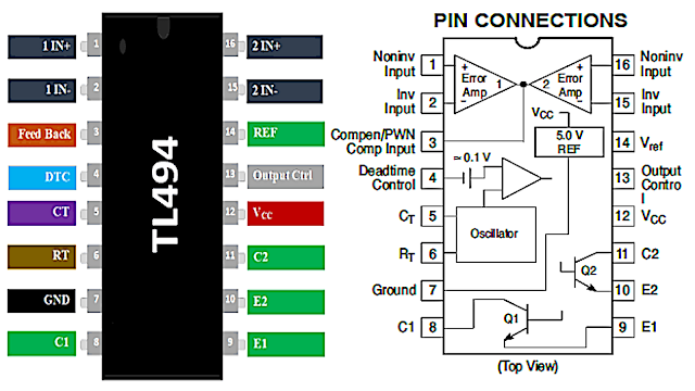
TL494 Pinout & Pin Configuration
 |
| TL494 pinout electrobuff.blogspot.com |
 |
| TL494 internal block diagram electrobuff.blogspot.com |
 |
| TL494 block diagram guide electrobuff.blogspot.com |
| Pin Name | Pin NO. | Pin Description |
| 1IN+ | 1 | Noninverting input to error amplifier 1 |
| 1IN | 2 | Inverting input to error amplifier 1 |
| 2IN+ | 16 | Noninverting input to error amplifier 2 |
| 2IN- | 15 | Inverting input to error amplifier 2 |
| C1 | 8 | The collector terminal of BJT output 1 |
| C2 | 11 | The collector terminal of BJT output 2 |
| CT | 5 | The capacitor terminal used to set the oscillator frequency |
| DTC | 4 | Dead-time control comparator input |
| E1 | 9 | The emitter terminal of BJT output 1 |
| E2 | 10 | The emitter terminal of BJT output 2 |
| FEEDBACK | 3 | Input pin for feedback |
| GND | 7 | Ground |
| OUTPUT CTRL | 13 | Selects single-ended/parallel output or push-pull operation |
| REF | 14 | The 5-V reference regulator output |
| RT | 6 | The resistor terminal used to set the oscillator frequency |
| VCC | 12 | Positive Supply |
How does the TL494 PWM controller work?
As mentioned earlier, it is a fixed frequency and variable duty cycle dual PWM control circuit. It does not require any external components to operate except a few resistors and capacitors for an oscillator. This oscillator is responsible for generating a sawtooth waveform according to timing capacitor CT. This TL494 IC generates signals by comparing a sawtooth waveform with two control signals of the error amplifiers. The output signal will be on during the time when sawtooth voltage is greater than the voltage at error amplifiers outputs. You can see a block diagram given above.
- Output signal low: if sawtooth voltage less than the control signal voltage
- Output signal High: if sawtooth voltage greater than the control signal voltage
Pulse-Steering Flip-Flop transfers the PWM output signal to output transistors.
How to select TL494 Oscillator Frequency?
In the last section, we see that the oscillator is mainly responsible for generating sawtooth waveform. This sawtooth waveform used for deadtime control and PWM comparator amplifiers. Therefore, the frequency of the oscillator determines the frequency of output signals. Now, we will see how to choose the frequency of an oscillator.
We can select frequency by selecting suitable values of RT resistor and CT capacitor. We can select the capacitor and resistor values according to this formula:
Frequency= 1/ RT X CT
 |
| TL494 Frequency calculation Formula electrobuff.blogspot.com |
TL494 Applications
- Switch Mode Power Supplies
- High Power Inverters
- Power Electronics Applications
- Power factor correction meters
- Desktop and Portable applications
TL494 Packages
This IC is available in four different 16 pin packages such as SOIC, PDIP, SOP, TSSOP. You can check the datasheet for the 2D physical dimension diagram of these packages.
.png)


.png)


.png)


very well sir
ReplyDelete